Showing posts with label Servo motor. Show all posts

Tuesday, April 12, 2011

Arduino and Tx/Rx system

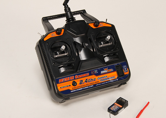
In the previous article the PWM signal was described, which used to control servo motors. Today we will use the following Transmitter/Receiver (Tx/Rx) and the Arduino to read PWM signals.
Tx/Rx manufactured by www.HobbyKing.com
The above Tx/Rx systems usually used for controlling airplanes, helicopters and other remote vehicles. This one has 6 channel, which means it can control 6 different motors (servos and other types).
In the following picture you can see 7 row of pins(6 channels + battery).
Receiver
This Tx/Rx system comes without any documentation, so the only way to get more information is to google the Internet. Actually I thought that the receiver gets it's power from the battery pins(I don't know why 3 pins) and generate appropriate PWM signals on all channels, but I discover the following:
If connect only(without battery connected) channel pins to appropriate Arduino pins(+5V to +5V, Gnd to Gnd, and Signal to digital port 2), then the receiver will work and on the signal pin it generates PWM signal, coming from transmitter. To read the signal, connect 2nd channel pins to Arduino appropriate pins(The 2nd channel corresponds to throttle). Connect signal pin to Arduino digital pin 2.

The Arduino has a PulseIn function, which can be used to read the PWM pulse width. The micros function returns the number of microseconds since the Arduino began running. Compile and upload the following code and run it then switch-on the transmitter.
Before switching on the transmitter, the time interval is about 100ms, which is equal to 50ms timeout time + Serial print times, and the pulse width is 0(no signal). When the transmitter switched-on, the pulse width is near to 1460us and time interval reduced to ~66ms, which now is equal to ~20ms period time + Serial print times.
Switching-on transmitter
And this is the screenshot of Serial output when the throttle is changed by moving joystick up and down.
Moving throttle joystick up/down
That's all.

Monday, April 11, 2011

Servo motors and PWM

In the previous article we use Arduino's Servo library to control servo motors. Today we will try to understand how Servo library works. The servo motors are controlled by digital PWM signals. Those signals are square waves with a period about 20-22ms. And the pulse width(usually ~0.5-2.5ms) is corresponds to the position of servo motor.
This a sample signal
There is another overloaded Servo.attach function (used to attach servo to the pin) with 3 arguments:
    servo.attach(pin, min, max) 
(min,max) are the pulse minimum and maximum widths in microseconds. Default values are 544us and 2400us(you can also check them in the <Arduino-dir>\libraries\Servo\Servo.h file, MIN_PULSE_WIDTH and MAX_PULSE_WIDTH macros). Most of hobby servo motors have those default values, but if your servo doesn't work, then you need to dig into the documentation to find out right values. This Servo library takes minimum 20ms for signal period: see <Arduino-dir>\libraries\Servo\Servo.h file:
    #define REFRESH_INTERVAL    20000 // minumim time to refresh servos in microseconds
That's all.

Tuesday, March 29, 2011

Arduino and Servo motors

Arduino has a Servo library which allows to control servo motors. Today we will use the following small servo motor and write a program, which read a angle value from Serial port and rotate servo motor according to it.
This is the source code of program

Compile and upload above code to Arduino, then connect control pin(gray wire) of Servo motor to Arduino pin 11, connect black wire to Gnd of Arduino and red wire to +5V. This is how it looks:

And this is a video demonstration of moving Servo 0 -> 90 -> 180 -> 0 -> 90: