Showing posts with label Arduino. Show all posts

Saturday, May 7, 2011

Arduino Uno: Upload new firmware to the Atmega8U2

In the previous article it is described how to put Arduino Uno into DFU mode. To upload a new firmware the dfu-programmer is needed (Ubuntu users: sudo apt-get install dfu-programmer). Windows user can try FLIP software from Atmel. You can upload already compiled hex code from Arduino package or build it from sources (/usr/share/arduino/hardware/arduino/firmwares/arduino-usbserial/Arduino-usbserial-uno.hex or the latest one from github https://github.com/arduino/Arduino/raw/master/hardware/arduino/firmwares/arduino-usbserial/Arduino-usbserial-uno.hex). The steps are:
Put Uno into DFU mode,
sudo dfu-programmer at90usb82 erase
sudo dfu-programmer at90usb82 flash .../Arduino-usbserial-uno.hex
sudo dfu-programmer at90usb82 reset 
reconnect the USB cable.

The LUFA library is needed for building hex file from sources. Download the lib version 100807. Current sources doesn't compile with the latest LUFA(version 101122).
mkdir uno
cd uno
cp -r /usr/share/arduino/hardware/arduino/firmwares/arduino-usbserial ./
wget http://www.fourwalledcubicle.com/files/LUFA/LUFA-100807.zip
unzip LUFA-100807.zip
mv LUFA\ 100807/ LUFA
Fix the LUFA path in "arduino-usbserial/makefile":
     # Path to the LUFA library
     LUFA_PATH = ../..
change to
     # Path to the LUFA library
     LUFA_PATH = ../LUFA
make all
After the successful build the file "Arduino-usbserial.hex" is created. Now you can upload this hex file using above steps.

P.S. After the new firmware upload try to upload and run something using Arduino IDE(the Blink example), to make sure the "USB to Serial converter" firmware works fine.

That's all.

Tuesday, April 26, 2011

Arduino Uno

Arduino Uno is the latest version of the Arduino boards (next to the Duemilanove). The major difference from the previous board is in that it uses the Atmega8U2 micro-controller (instead of FTDI) for communicating with a computer. The Atmega8U2 is programmed as a USB to serial converter by default, but it can be programmed as any other USB devices (keyboard, mouse, joystick and etc...).
Arduino Uno
To upload a new firmware to the Atmega8U2, we need to reset the chip and put it into a DFU mode. There is a description in the Ardunio site how to do that. It can be done easily using 2 M/M jumper wires
M/M jumper wire
Instead of using ground pads(from the description in Arduino site), we can use Arduino's GND pins.
1)Connect Arduino Uno to the computer
2)Hold first wire as pictured in the below image.
3)Connect second wire.
4)Remove second wire then remove first.
Now your Arduino is in DFU mode
The Device manager (in windows 7)
To return to the USB to serial converter mode, just disconnect and connect Arduino.
The upload of a firmware will be in the next article.

Monday, April 25, 2011

Flightgear and Tx/Rx system

In the previous article the Flightgear's aircraft controlled using external program and in another article the Tx/Rx system connected to computer using Arduino. Today we will use those knowledges to connect Tx/Rx to Flightgear. Download the project from github and do the following steps.
1)Copy protocol files from Protocol/ to C:\Program Files (x86)\FlightGear\data\Protocol\
2)Compile and upload Rxreader/Rxreader.pde to the Arduino.
3)Connect Receiver to the Arduino
4)Run the C# program and connect to the Arduino and click to calibrate (this determines min-max values). When min-max values determined, finish the calibration.
5)Run Flightgear with the following arguments.
"C:\Program Files (x86)\FlightGear\bin\Win32\fgfs" ^
 "--fg-root=C:\Program Files (x86)\FlightGear\data" ^
 "--aircraft=Malolo1" ^
 "--generic=socket,out,10,127.0.0.1,49001,udp,outputprotocol" ^
 "--generic=socket,in,10,,49000,udp,inputprotocol" ^
 "--timeofday=noon"
6) Connect to Arduino, and connect the input and the output to Flightgear.
 
7)Try do not crash the airplane :)
That's all.

Tuesday, April 12, 2011

Arduino and Tx/Rx system

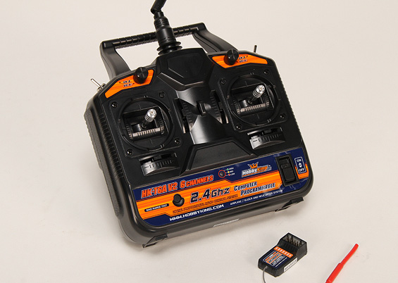
In the previous article the PWM signal was described, which used to control servo motors. Today we will use the following Transmitter/Receiver (Tx/Rx) and the Arduino to read PWM signals.
Tx/Rx manufactured by www.HobbyKing.com
The above Tx/Rx systems usually used for controlling airplanes, helicopters and other remote vehicles. This one has 6 channel, which means it can control 6 different motors (servos and other types).
In the following picture you can see 7 row of pins(6 channels + battery).
Receiver
This Tx/Rx system comes without any documentation, so the only way to get more information is to google the Internet. Actually I thought that the receiver gets it's power from the battery pins(I don't know why 3 pins) and generate appropriate PWM signals on all channels, but I discover the following:
If connect only(without battery connected) channel pins to appropriate Arduino pins(+5V to +5V, Gnd to Gnd, and Signal to digital port 2), then the receiver will work and on the signal pin it generates PWM signal, coming from transmitter. To read the signal, connect 2nd channel pins to Arduino appropriate pins(The 2nd channel corresponds to throttle). Connect signal pin to Arduino digital pin 2.

The Arduino has a PulseIn function, which can be used to read the PWM pulse width. The micros function returns the number of microseconds since the Arduino began running. Compile and upload the following code and run it then switch-on the transmitter.
Before switching on the transmitter, the time interval is about 100ms, which is equal to 50ms timeout time + Serial print times, and the pulse width is 0(no signal). When the transmitter switched-on, the pulse width is near to 1460us and time interval reduced to ~66ms, which now is equal to ~20ms period time + Serial print times.
Switching-on transmitter
And this is the screenshot of Serial output when the throttle is changed by moving joystick up and down.
Moving throttle joystick up/down
That's all.

Monday, April 11, 2011

Servo motors and PWM

In the previous article we use Arduino's Servo library to control servo motors. Today we will try to understand how Servo library works. The servo motors are controlled by digital PWM signals. Those signals are square waves with a period about 20-22ms. And the pulse width(usually ~0.5-2.5ms) is corresponds to the position of servo motor.
This a sample signal
There is another overloaded Servo.attach function (used to attach servo to the pin) with 3 arguments:
    servo.attach(pin, min, max) 
(min,max) are the pulse minimum and maximum widths in microseconds. Default values are 544us and 2400us(you can also check them in the <Arduino-dir>\libraries\Servo\Servo.h file, MIN_PULSE_WIDTH and MAX_PULSE_WIDTH macros). Most of hobby servo motors have those default values, but if your servo doesn't work, then you need to dig into the documentation to find out right values. This Servo library takes minimum 20ms for signal period: see <Arduino-dir>\libraries\Servo\Servo.h file:
    #define REFRESH_INTERVAL    20000 // minumim time to refresh servos in microseconds
That's all.

Tuesday, March 29, 2011

Arduino and Servo motors

Arduino has a Servo library which allows to control servo motors. Today we will use the following small servo motor and write a program, which read a angle value from Serial port and rotate servo motor according to it.
This is the source code of program

Compile and upload above code to Arduino, then connect control pin(gray wire) of Servo motor to Arduino pin 11, connect black wire to Gnd of Arduino and red wire to +5V. This is how it looks:

And this is a video demonstration of moving Servo 0 -> 90 -> 180 -> 0 -> 90:

Monday, March 28, 2011

How many G my car can pull?

In the previous article we study how to work with ADXL335 accelerometer. Today we will use it to measure car's acceleration. This is a sample program which get the values from sensor and send them through serial port to the computer. It measures every 20ms and do it 1000 times.

Now lets connect ADXL335 to the Arduino and then compile and upload the above code.
Sensor placed in such way that Z axis is directed to front of car.(You can see it in the picture, on top of red box).

I run the program, type something and press enter in the Serial Monitor and then drive as fast as possible and then brake the car. Copy the values to the Google Docs Spreadsheet and create a chart for the values of Z axis (in which direction the acceleration occurs). But before creating charts lets understand how those numbers map to the real acceleration values in g. The Z axis can be directed downward and measure value (+1g), then direct it upward and measure again(-1g) and taking account that the measured values dependance on acceleration is linear, calculate which value correspond to 0g and which interval correspond to 1g interval. I get following results (approximate results)
    0g --  355
    1g interval -- 70 interval
The measured values also contain a lot of noise, so we need to filter out them.

This is unfiltered chart: Z_i


This is filtered and converted to G chart: ((Z_i + Z_i+1) /2 - 355) / 70


This is filtered(another filter) and converted to G chart: ((Z_i + Z_i+1 + Z_i+2) / 3  - 355) / 705

In the above chart you can see the shift of gear from 1 to 2 and then brake. After car stops and acceleration is 0.

Tuesday, February 15, 2011

Arduino and EEPROM

  EEPROM is a non-volatile memory on the Arduino. It's like a HDD in the computer, can hold the data when board is turned off, but has too little memory :(. The EEPROM size of Arduino Duemilanove's Atmega328 is only 1024 byte.
  Arduino IDE has simple EEPROM library, which has only 2 functions: "read" and "write". Lets write a demo program which will save to EEPROM anything received from serial port and if the 's' symbol is received it will return all stored symbols.

Monday, February 14, 2011

ADXL335 Accelerometer

Accelerometer is a sensor that measure linear acceleration. Today we will use ADXL335 accelerometer, we will write a program to display the measured values of acceleration of all 3 axes.
ADXL335 on a board(Manufactured by Sparkfun.com)
You can see axis scheme on the board, the x and y axises directions are clear, and the z axis direction is point out of the board. Remember this sensor has a sensing range of +/-3g, so you can't measure a higher accelerations :). But it is not a big disadvantage, because the calculation shows that more than 100 km/h we can get during 1 second of 3g acceleration. If you want to check it but you are lazy to do, you can use http://www.wolframalpha.com(3 * gravitational acceleration * 1 second in km/h).
The interface of this device is analog: The voltages on X(Y,Z) port depends on the linear acceleration throughout X(Y,Z) axis. The Arduino board has 6 analog-in ports, we can use 3 of them(0,1,2) to connect to X,Y,Z ports of ADXL335.
Analog ports

So lets open the Arduino IDE and write a simple program, which will periodically read the values on analog ports and send trough the Serial port.

In this program analogRead function read the voltage on the pin and return the integer value between 0 and 1023.
On the computer side we will read the information coming through Serial port an show the values on 3 horizontal progress bars.

This is C# code of program

Be careful, connect ADXL335 to the Arduino board, before connecting them to the PC, otherwise the board will hang and only solution is reconnecting.

This is a short video how it runs.

Saturday, December 25, 2010

Arduino and C#

In the previous article we use Serial Monitor tool to view received data and send data through serial port. Today we will write our standalone Serial Monitor like tool in C#.
We will create new Window Forms Application and add the following components from the picture
C# serial tool

The refresh button will add com ports to the combo box. Let see how it is implemented

Now when we have the name of serial port, we need to create serial port object and connect it, then send/receive data.

Be careful, do not write data directly to the output text box in read_serial_port function, because you can't access a control created in another thread. To do that you need to invoke some updater function like this

Lets write the "echo" program in Arduino and see how our tool works.

Now we will upload above code to Arduino and run the tool. And it works. hurray:)
Working serial tool
Thats all. Next time we will connect accelerometer to the Arduino and write a tool to see values of sensor on the computer.

Friday, December 24, 2010

Arduino and The Serial port

Arduino Duemilanove has an on-board serial port(connected to pins 0(RX) and 1(TX)), which used for communication with a computer or other device. It also used for uploading of the program to the board. Actually the board and the computer connected with USB port, but on board side there is a USB to Serial converting chip, and on computer side the driver convert Serial to USB(this is why on the Arduino software the type of connection port is COM port).

The Arduino software(IDE) has a "Serial Monitor" tool, for receiving and sending data through serial port. So we can using it see how the next program will run. We will write a simple program sending "Hello World" text through serial port.
// program: send "Hello World" through serial port
void setup()
{
  Serial.begin(9600);              //switch on serial port and set the speed to 9600 bits per second
  Serial.println("Hello World"); // send a text ...
}
void loop()
{
  // nothing to do
}
Copy above code to a new project, verify and upload it, then open Serial monitor. Set the connection speed to 9600(the speed set in the program). After reseting the board you will see the "Hello World" on the screen.
Serial monitor
Now lets try to enhance our program to use two way communication.
// program: send "hello World" through serial port
void setup()
{
  Serial.begin(9600);
}
void loop()
{
  if (0 < Serial.available()) // See is there any coming data
{
    int data = Serial.read();     // read first byte
    Serial.println(data, HEX); // print data in HEX
  }
}
The program see is there any data to read, if there is, read it and return HEX value. So lets run it and see how it works.
As you can see it prints the ASCII HEX values of inputed characters :).

There are many Arduino boards, the one we using for our programs is Arduino Duemilanove, which has only one serial port. But there are Arduino Mega boards, which has 4 serial ports. Those serial ports can be accessed the same way, changing Serial with Serial1, Serial2 and Serial3.
Arduino Mega 2560
More information about Serial can be found at Arduino site(http://arduino.cc/en/Reference/Serial).

Wednesday, December 22, 2010

Arduino and The "Hello World!"

Arduino is a hardware electronics platform for easy prototyping and for easy creation of automated systems, more information can be found here www.arduino.cc.
This is it.
Arduino Duemilanove (2009 version)
As you can see it has USB port(yes! It is USB, it is standard type B) to connect with a computer. We need Arduino software to work with it (http://arduino.cc/en/Main/Software).
It is a tradition to write "Hello World" to the screen as a first program. But our hardware hasn't any screen :(. So we need to think something different. There is a simple tutorial at Arduino web site http://www.arduino.cc/en/Tutorial/BlinkingLED which is described as the "Hello world" of Arduino. So let see what it does. It uses an external LED, which connected to the board and periodically switch it on and off. But there is a build-in LED connected to the pin 13, so we can use it instead of connecting external one.
Built-in LED
The programming language is based on C++(actually it is based on Wiring...), but it doesn't mean you can write a program including iostream, cining, couting and etc ...
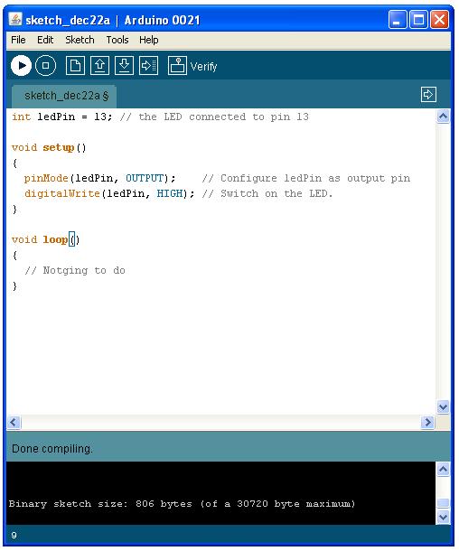
The console c++  programs has a mandatory "main(argc, argv)" function, on the Arduino there are two mandatory functions void setup() and void loop(). The first function will called when the Arduino is powered on(or reseted), and then the second function called repeatedly in infinite loop. So lets write a simple program which switch-on the built-in LED.
// Program: switch on the LED
int ledPin = 13; // the LED connected to pin 13
void setup()
{
pinMode(ledPin, OUTPUT); // Configure ledPin as output pin
digitalWrite(ledPin, HIGH); // Switch on the LED.  
}
void loop()
{
// Nothing to do
}

The build-in LED connected to 13th pin, so we need to configure it as an output pin. digitalWrite function write digital 1(+5V), which will switch on the LED.
Now it is time to run it. First of all create a new project in Arduino Software
New Project
copy above source code and verify it(it compiles the code)
Verify
Now the time is to connect Arduino hardware to the computer and then choose the right board type and serial port.
Select board type
Now verify it again and upload.
Upload
It automatically start to run. It can be rerun(reseted) by on-board reset button
On-board reset button
Now we will enhance our program, to switch on/off the LED periodically
// Program: periodically switch on/off the LED
int ledPin = 13; // the LED connected to pin 13
void setup()
{
    pinMode(ledPin, OUTPUT);   // Configure ledPin as output pin
}
void loop()
{
    digitalWrite(ledPin, HIGH);  // switch on the LED.  
    delay(1000);                       // delay 1000 milliseconds
    digitalWrite(ledPin, LOW);   // switch off the LED
    delay(1000);                       // delay 1000 milliseconds
}

Thats all, next time we will write a program using Arduino's serial port.