 |
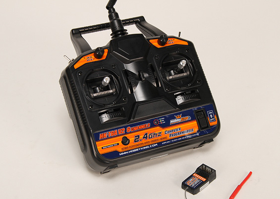
| Tx/Rx manufactured by www.HobbyKing.com |
In the following picture you can see 7 row of pins(6 channels + battery).
 |
| Receiver |
If connect only(without battery connected) channel pins to appropriate Arduino pins(+5V to +5V, Gnd to Gnd, and Signal to digital port 2), then the receiver will work and on the signal pin it generates PWM signal, coming from transmitter. To read the signal, connect 2nd channel pins to Arduino appropriate pins(The 2nd channel corresponds to throttle). Connect signal pin to Arduino digital pin 2.
The Arduino has a PulseIn function, which can be used to read the PWM pulse width. The micros function returns the number of microseconds since the Arduino began running. Compile and upload the following code and run it then switch-on the transmitter.
Before switching on the transmitter, the time interval is about 100ms, which is equal to 50ms timeout time + Serial print times, and the pulse width is 0(no signal). When the transmitter switched-on, the pulse width is near to 1460us and time interval reduced to ~66ms, which now is equal to ~20ms period time + Serial print times.
 |
| Switching-on transmitter |
 |
| Moving throttle joystick up/down |
Hi Mkrtich,
ReplyDeleteThis post is very helpful to me. I am interested to make the same thing. However I am newbie to Arduino. Would you please teach me which Arduino board is used and how do you connect the servo signal to the Arduino board?
Regards,
Donald
Hi Donald,
DeleteI tried with Arduino UNO and Duemilanove. In the article it is described how to connect servo signal pins to the board (+5V to +5V, Gnd to Gnd, and Signal to digital port 2)
Regards,
MKo.
Thanks Mkrtich. I will get one of them.
ReplyDeleteThank you for your help.
Regards,
Donald